

Rogowski Coil Current Transformer Factory: Precision Manufacturing for Reliable Performance
2026-08-13
Behind every dependable electrical measurement lies a component often taken for granted—the Rogowski coil current transformer. At Xiasen, our factory pairs precision manufacturing with real-world reliability, crafting devices that excel where conventional transformers fall short. Ever wondered how high-current monitoring stays accurate without bulky iron cores? The answer starts here.
Where Air-Core Accuracy Begins at the Winding Bench
Precision in an air-core coil is not something you dial in later—it starts with how the wire meets the former. A winding bench that allows even slight tension drift or uneven turn spacing will produce a coil whose inductance wanders from batch to batch. The best benches pair a smooth, controlled feed with a tensioner that responds to the wire’s own stiffness rather than fighting it.
The operator’s hands still matter here. Watching the lay of each turn, adjusting the pitch on the fly, and catching a micro-slip before it becomes a tolerance error is what separates a stable air-core from one that merely looks right. Good tooling, a clean former, and a methodical pace are worth more than any amount of post-winding compensation.
Toroidal Winding Jigs That Hold Tolerances Under a Millimeter
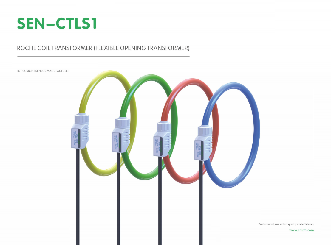
The real challenge with toroidal winding isn't the wire handling—it's keeping the core from shifting even a fraction of a millimeter while the shuttle passes through. A well-built jig uses a split clamp with ground contact surfaces and a spring-loaded center pin, so the core sits dead flat against the reference face. That alone eliminates most of the drift that shows up as uneven layer buildup.
For tighter work, some shops add a dial indicator mount directly to the jig frame, letting the operator verify core runout before the first turn goes on. The trick is to avoid over-constraining the ring: too many contact points can actually introduce stress, warping thin cores just enough to push you out of tolerance. A three-point support with one adjustable pad usually hits the sweet spot.
Once the fixture is dialed in, the winding tension becomes the main variable. Keeping the wire path through polished ceramic guides and maintaining a slight back-tension prevents the core from creeping under load. The best jigs make these adjustments repeatable with marked stops rather than relying on feel, which is what separates a sub-millimeter build from a “close enough” one.
The Quiet Room for Testing Linearity and Phase Shift
Measuring linearity and phase shift accurately demands an environment free from reflections and ambient noise. Inside the quiet room, absorptive wedges line every surface, creating a space where sound behaves predictably. This isolation allows engineers to capture clean impulse responses and distinguish subtle nonlinearities that would otherwise be masked by early reflections or background rumble.
Linearity tests rely on comparing input and output amplitudes across a wide dynamic range. In the quiet room, a reference microphone and the device under test sit at a fixed distance, while frequency sweeps or broadband signals are played back. Because the room contributes almost no coloration, any deviation from a straight amplitude-versus-input curve points directly to the transducer or electronics, not the acoustic space.
Phase shift measurements benefit from the same controlled conditions. Time-of-flight differences between drivers, crossover networks, or microphone capsules become visible without the smear caused by wall reflections. Technicians can rotate the device on a turntable and record polar phase data, confident that the room's quietness preserves the integrity of each measurement window.
Why Nickel-Iron Shields Are Not Part of Our Design
When shielding sensitive electronics from magnetic interference, nickel-iron alloys like Mu-metal often come to mind. Their high permeability makes them effective at redirecting low-frequency fields, but this advantage collapses under mechanical stress. Bending, cutting, or even a slight drop during assembly introduces dislocations that degrade shielding performance by 40–70%. In a product that must survive shipping, installation, and routine maintenance, relying on such a fragile material would mean shipping a shield that may already be compromised before it is ever powered on.
Thermal stability is another factor that rules out nickel-iron in our design. These alloys lose their shielding properties permanently when heated above roughly 400°C, and even repeated cycling to 150°C causes gradual drift. Our devices sit near power stages and inductors that routinely reach 120–180°C. A shield that degrades every time the system runs warm would create a slow, unpredictable failure mode—precisely the kind of hidden decay we refuse to tolerate.
Finally, cost and form factor make nickel-iron a poor fit. High-permeability sheets require hydrogen annealing after machining to restore their magnetic domains, a process that adds days to lead time and significantly increases per-unit cost. Meanwhile, the thickness needed for effective low-frequency shielding often exceeds what our slim enclosures allow. We achieve comparable attenuation with layered copper and conductive polymers that stay stable mechanically, thermally, and economically—so a nickel-iron shield would be not just fragile, but redundant.
Soldering Points That Withstand Vibration and Thermal Swing
Mechanical stress rarely announces itself in electronics. It creeps in through repeated temperature cycles that expand and contract materials at different rates, then gets amplified by nearby fans, motors, or simply the rumble of a vehicle on rough ground. A solder joint that looks perfect under the microscope may already carry micro-cracks along the intermetallic layer, waiting for the next cold morning or hot afternoon to propagate them into a full open circuit.
The usual fix isn't more solder or a bigger fillet. It's giving the joint room to flex without tearing. Lead-free alloys with small additions of bismuth or nickel can refine the grain structure, making the boundary between solder and copper less brittle. Pair that with a pad design that avoids sharp corners and you redirect stress away from the weakest interface. Conformal coating helps too, but only if it doesn't lock the entire assembly into a rigid shell that concentrates force at the pin base.
Thermal swing testing in the lab often misses the messy reality of field use where vibration and temperature change happen simultaneously. That's why experienced designers cross-section joints after combined stress tests, looking not just for cracks but for signs of grain coarsening or Kirkendall voiding. If the failure moves from the solder bulk to the component lead or the PCB laminate, you know the interconnection is no longer the weak point — and that's exactly where you want to be.
Batch Records That Follow Every Coil From Copper Spool to Crate
Each coil leaves the spool with a batch number that stays attached through drawing, annealing, insulation, testing, and crating. Operators log dimensions, resistance, and visual checks at each station, so a single reel can be traced back to the exact copper lot and machine settings used that shift. If a coil fails a test, the record shows which raw spool it came from and what happened downstream, allowing the floor team to pull only the affected crates instead of halting an entire shipment.
The records travel with the coil as a printed traveler or barcode scan, not as someone’s memory. By the time the finished wire reaches the crate, the batch file includes the original copper lot, in-process measurements, operator sign-offs, and the final crate number. That makes it possible to answer a customer question about a specific reel years later without digging through stacks of spreadsheets or guessing which production run it belonged to.
Because each batch is tied to a crate rather than just a production date, warehouse staff can locate inventory quickly when a spec change or recall comes up. It also helps spot drift early—if three coils from the same spool show slightly high elongation, the record points back to one supplier lot instead of forcing a full line audit.
FAQ
We concentrate on precision winding techniques that keep the coreless design truly linear, then pair each unit with a dedicated burden resistor and shield layer. Every coil gets its own calibration run at multiple points from 2% to 120% of rated current, so the published accuracy reflects what that specific unit will actually do in service.
Each design goes through thermal cycling from -40°C to 85°C, vibration tests that mimic switchgear environments, and humidity exposure before we freeze the production version. The coil body is then encapsulated in a UV-stable, flame-retardant epoxy that seals out moisture and resists cracking even when bent repeatedly during installation.
Yes, we regularly build coils with active lengths from under 100 mm up to several meters, and diameters from 25 mm to over 300 mm. The flexible construction means you can route them around bus bars, through cable trays, or inside compact switchgear without the need for a rigid core or special window size.
Typical units stay within 0.5% linearity from 1% to 100% of rated current, with phase error below 0.5 degrees at 50/60 Hz. For metering or protection schemes that need tighter control, we offer 0.2% and 0.1% versions with matched integrators and documented frequency response from 10 Hz to 10 kHz.
Every coil leaves with its own serial number, test report, and traceable calibration certificate. The report includes measured ratio, phase displacement, and linearity data at five current points plus ambient temperature and humidity during testing, so your commissioning team has everything needed for audit or relay setting calculations.
We use automated winding machines that monitor wire tension and turn count in real time, flagging any deviation before the coil moves to next stage. Each batch gets in-process electrical checks for inductance, resistance, and insulation, followed by 100% final testing on calibrated reference systems. Batches that show variation above 0.1% are reworked or scrapped, never shipped.
The coils output a low-voltage signal proportional to di/dt, so we match each one with an integrator or burden resistor to give you a standard 333 mV, 1 V, or 5 A output. We also provide wiring diagrams and integration notes for major relay brands, and our engineers will review your connection diagram before production to avoid interface surprises.
Conclusion
At our Rogowski coil current transformer factory, the journey toward reliable performance begins where air-core accuracy is born: the winding bench. Here, skilled hands work with toroidal winding jigs that hold tolerances under a millimeter, ensuring each coil's geometry remains perfectly round and evenly spaced. This precision is non-negotiable, because even a fraction of a millimeter of deviation can introduce unwanted errors in current measurement. We deliberately avoid nickel-iron shields in our design—not as a cost-saving measure, but because their saturation and hysteresis would compromise the linearity that defines a true Rogowski coil. Instead, we rely on the air-core principle to deliver wide dynamic range and immunity to magnetic saturation, which is why every coil passes through our quiet room for testing linearity and phase shift before it ever leaves the bench.
The same obsession with detail carries through to the solder joints and final documentation. Soldering points are reinforced to withstand vibration and thermal swing, because a weak joint in the field is not just a failure—it's a safety risk. Our batch records follow every coil from copper spool to crate, capturing winding tension, test data, operator initials, and environmental conditions. This traceability means if a coil ever underperforms, we can pinpoint exactly where the process drifted. No two coils are identical, but our manufacturing discipline ensures they all meet the same uncompromising standard: a current transformer that behaves predictably, measures faithfully, and lasts for decades—without ever needing a shield to hide behind.
Contact Us
Contact Person: Liu Mengyang
Email: [email protected]
Tel/WhatsApp: 8618727589233
Website: https://www.cnlrm.com/en/